Scrolling Meshtastic Messages on an 8x32 WS2812B LED Panel: Custom Firmware, MQTT, and the Decryption Part Nobody Explains
There's a Meshtastic node on my desk. Messages bounce around the mesh all day and I have no idea until I check the app, which I often forget to do. A notification on my phone helps approximately never because the phone is always in a different room.
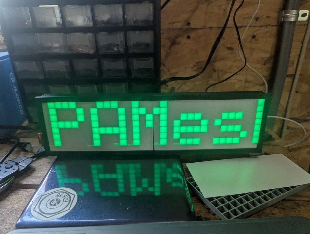
So I built a ticker. An ESP32-C6, a WS2812B 8x32 LED panel, custom C++ firmware that subscribes to Meshtastic's encrypted MQTT topic, decrypts packets on-device using AES-128-CTR, parses the protobuf, and scrolls messages as colored text. It also shows a live NTP clock when the mesh is quiet, runs scheduled messages on a timer, and has a web interface that you'll actually want to look at.
The parts bin had been staring at me for months. A free Saturday did the rest.
This is the full build guide: hardware, wiring, how the firmware works under the hood, flashing from zero, MQTT config, and what to do when the display shows garbage.
What It Does
The short version: the ESP32 connects to WiFi, subscribes to the Meshtastic MQTT broker, decrypts incoming packets, and scrolls text messages across a 32x8 grid of WS2812B LEDs. Callsign: message text. Full color, configurable.
The longer version has a few features worth knowing about upfront:
- Message display — incoming Meshtastic text messages scroll as Callsign: message. Node names are learned passively from NodeInfo packets in the traffic stream. First time a node transmits:
!XXXXXXXX. After it broadcasts its name: callsign. - NTP clock — when no messages are queued, the panel shows the current time in H:MM format. Synced on boot. As soon as a message finishes scrolling, the clock reappears. This is the feature that turned it from a thing I built into a thing I actually want on my desk permanently.
- Scheduled messages — set a custom message and an interval in minutes. The message scrolls at that interval whether or not mesh traffic is coming in. Good for a lobby sign or any deployment where you want context between messages.
- Date display — same idea, scrolls the full date every N minutes.
- Boot test — red, blue, green comet across all 256 LEDs on startup. If LEDs are dark or wrong colors, fix the wiring before debugging anything else.
How It Works Under the Hood
Skip this section if you just want to build the thing. Read it if you want to understand or modify the firmware.
The MQTT Topic
The firmware subscribes to:
msh/nepa/2/e/LongFast/#| Component | Meaning |
|---|---|
msh | Meshtastic namespace |
nepa | Region — NEPAMesh uses msh/nepa instead of the default msh/US to keep traffic on our broker |
2 | Protocol version |
e | Payload type — encrypted binary protobuf. We decrypt on-device rather than using the /json decoded topic |
LongFast | Channel name |
# | MQTT wildcard — catches all node IDs |
The Packet Pipeline
Each MQTT payload is a serialized ServiceEnvelope protobuf. Four stages from bytes to LED:
- Envelope parse — unwrap ServiceEnvelope, extract inner MeshPacket bytes
- Packet parse — pull from_node (field 1), packet_id (field 6), and either
decoded(field 4, already plaintext) orencrypted(field 8, needs decryption) - AES-128-CTR decrypt — if encrypted, decrypt with default Meshtastic key and nonce built from packet_id + from_node
- Data dispatch — extract portnum and payload; portnum 1 = text message, portnum 4 = NodeInfo, everything else dropped
No protobuf library. The parser is a hand-rolled varint decoder, fixed32 reader, and skip function. Saves ~50KB of flash, no dependency to keep updated. Every length field is bounds-checked — a malformed or malicious packet drops cleanly.
AES-128-CTR Nonce
The 16-byte nonce is constructed from packet metadata:
nonce[0..3]  = packet_id  (uint32, little-endian)
nonce[4..7]  = 0x00000000
nonce[8..11] = from_node  (uint32, little-endian)
nonce[12..15]= 0x00000000
The default LongFast key (AQ== in base64) is baked into MESH_KEY[] in main.cpp. It's not a secret — it's the same 16 bytes on every stock Meshtastic device. Custom channel PSK? Swap in your 16 bytes and recompile. One array, one change.
Clock and NTP
A background task syncs to NTP on boot using your configured UTC offset. Once synced, the display loop checks whether anything is queued. If the queue is empty, it shows the current time in H:MM format, updating every minute. The [CLK] NTP synced log line confirms it's working. Until NTP syncs, the clock is suppressed and the panel stays dark between messages — you won't see a wrong time.
Two scheduled timers run independently in the background:
- Custom message — set a message and an interval in minutes. Every time the clock hits a minute divisible by that interval, the message scrolls. Set interval to 0 to disable.
- Date display — same mechanism, scrolls the current date in long form ("May 21, 2026") every N minutes. If the custom message and date are both scheduled for the same minute, the date is skipped so they don't overlap.
Both are configurable from the web UI without touching code. UTC offset, message, and both intervals all live in the CLOCK section of the settings page.
Display: Column-Major Serpentine Layout
WS2812B matrix panels wire LEDs column-major serpentine: column 0 runs one direction, column 1 reverses, and so on. The firmware's XY(x, y) function maps 2D coordinates to the 1D LED array index and handles both orientation flags at runtime:
static uint16_t XY(int x, int y) {
    int col = s_conn_right ? (MATRIX_W - 1 - x) : x;
    return (col & 1)
        ? (s_flip_y ? col*MATRIX_H + MATRIX_H-1-y : col*MATRIX_H + y)
        : (s_flip_y ? col*MATRIX_H + y            : col*MATRIX_H + MATRIX_H-1-y);
}
Both flags are settable from the web UI — no recompile. Right combination for the SVFISHKK panels as shipped: connector right, flip Y off.
Message Queue
Incoming messages go into a 4-slot ring buffer. A message scrolls s_repeat_count times (default 3, web-configurable) before the next dequeues. The web UI's Send Message box bypasses the queue — clears current scroll and starts immediately.
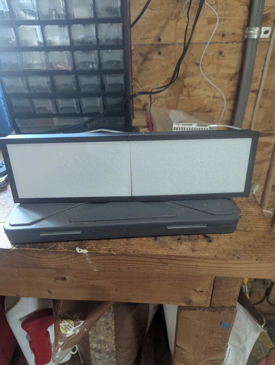
The Case (Optional, But Do It)
Bare WS2812B panels look like you're staring directly at individual LEDs. Hot spots, harsh edges, readable only at low brightness and only if you're looking straight at it. A diffuser fixes all of that immediately.
I used this frame from Printables: printables.com/model/709980. Two-piece design, no supports needed, the diffuser grid slots in and the whole thing clips together. Sliced and sent to the AD5X — took a few hours, zero babysitting.
The difference is not subtle. Text goes from 'grid of LED pinpricks' to 'readable sign from across the room' with a single piece of printed plastic. If you have a printer, do this part. It's worth the filament.
What You Need
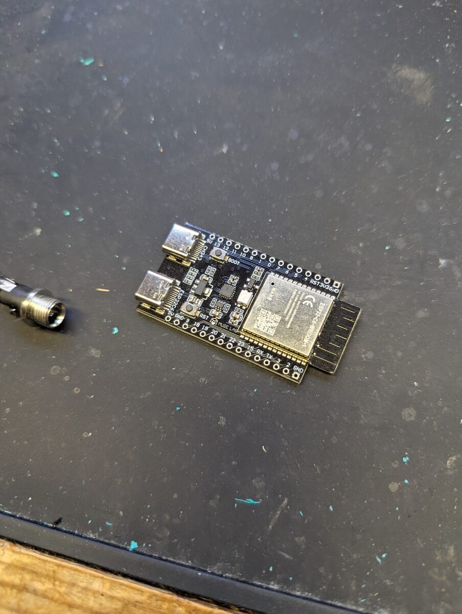
- ESP32-C6 DevKitC-1 (or any 38-pin ESP32 DevKit) — the firmware has build targets for both. The C6 uses a RISC-V core, WiFi 6, and native USB (shows up as
ttyACM0on Linux instead ofttyUSB0). ~$7–12. - WS2812B 8x32 LED matrix — the SVFISHKK panels (B0CY2R8FSL) come in a two-pack. You only need one, which conveniently means you have a spare for when you get overconfident with the power supply. The panels come with a JST-SM connector pre-installed. ~$16/pair.
- 5V power supply, 3A minimum — the panel can draw up to 3A at full white. At brightness 40/255 in green it's well under 500mA, but the supply still needs headroom for inrush. A 5V/3A USB-C brick works. Do not power the panel from the ESP32.
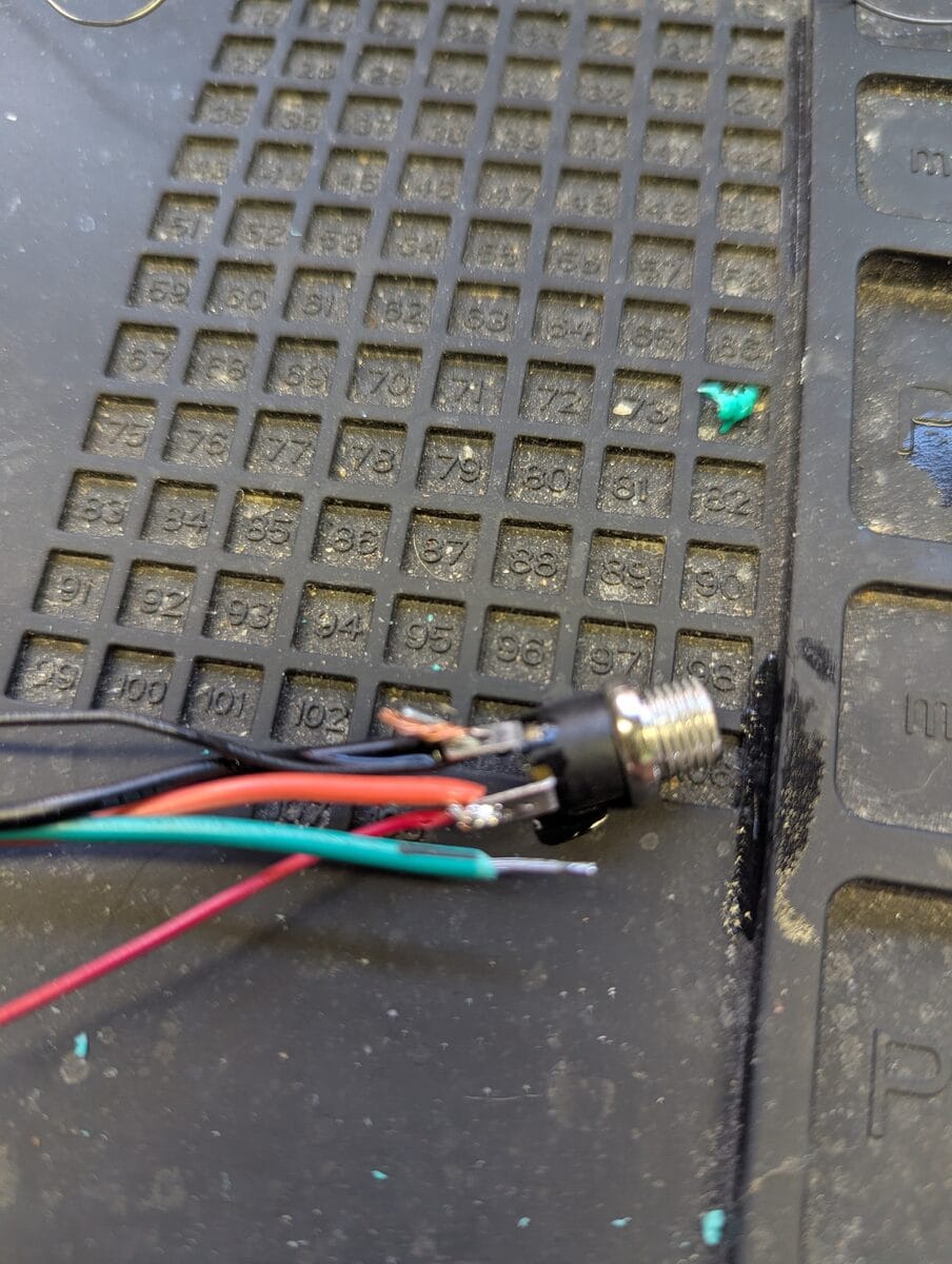
- Three wires — power, ground, data. Short ones.
- 300–500 Ω resistor (data line) and 100 µF cap (across panel power pads) — the resistor damps signal ringing on the 800 kHz NZR data line, the cap absorbs inrush current spikes. Both cost cents. I skipped them because I live dangerously and I have the spare panel. You should probably use them.
- USB cable — for the first flash. After that, updates go over WiFi.
Wiring
Three connections between the ESP32 and the panel. The panel's 5V comes from the external supply directly — not through the ESP32.
| From | To | Note |
|---|---|---|
GPIO 5 | Panel DIN | Via 300–500 Ω resistor in series |
GND | Panel GND | Direct |
| External 5V supply (+) | Panel 5V | Direct, ≥3A supply |
| External supply GND | ESP32 GND | Common ground tie — not optional |
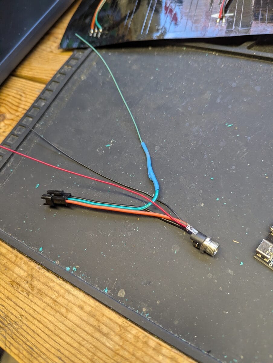
The ESP32 and LED panel are on separate power domains. Without connecting their grounds, the 3.3V data signal from GPIO 5 has no reference on the panel side. You'll get no response or garbage pixels, and it'll look like a firmware problem when it isn't.
Technically out of spec — WS2812B logic high threshold is 0.7 × VDD = 3.5V at 5V supply. In practice it works reliably with a short data wire and the series resistor. If you're seeing intermittent flicker on a longer run, a 74HCT245 level shifter fixes it.
Flashing the Firmware
PlatformIO project, Arduino framework, two board targets:
| Target | Board | Platform |
|---|---|---|
esp32dev | Any standard 38-pin ESP32 (Xtensa LX6) | Stock espressif32 platform |
esp32c6 | ESP32-C6 DevKitC-1 (RISC-V) | pioarduino platform fork — required for Arduino 3.x on C6 |
The
esp32c6 target pulls a pioarduino platform ZIP instead of the stock registry entry. Arduino-ESP32 3.x (required for C6) isn't in the official espressif32 package yet. PlatformIO handles the download automatically — first compile takes longer, subsequent ones are fast.Install VS Code and PlatformIO
VS Code from code.visualstudio.com, then Extensions (Ctrl+Shift+X) → search PlatformIO IDE → install. Let it finish downloading the toolchain before you try anything.
Linux: USB Permissions
Do this before you plug anything in, or you'll get a cryptic permission denied on upload and spend ten minutes convinced something else is wrong.
sudo usermod -a -G dialout $USER

curl -fsSL https://raw.githubusercontent.com/platformio/platformio-core/develop/platformio/assets/system/99-platformio-udev.rules \
  | sudo tee /etc/udev/rules.d/99-platformio-udev.rules

sudo udevadm control --reload-rules && sudo udevadm trigger
Log out and back in after usermod. Not close-the-terminal. Actually log out. Skipping this step is the single most common setup problem.
Native USB controller, not CH340/CP2102. Shows up as
/dev/ttyACM0 instead of /dev/ttyUSB0. PlatformIO handles it automatically.Windows: CH340 Driver
Standard ESP32 boards use a CH340 chip. If the board shows up in Device Manager with a yellow warning icon, install the CH340 driver, unplug, replug. The ESP32-C6 uses native USB and doesn't need it.
Configure config.h
Only required edit before first flash: open src/config.h, add WiFi credentials:
#define WIFI_SSID   "your-network-name"
#define WIFI_PASS   "your-wifi-password"
Everything else is web UI. The compile-time constants that can't be changed at runtime:
| Define | Default | Notes |
|---|---|---|
LED_PIN | 5 | GPIO pin to panel DIN — change here if your wiring differs |
NUM_LEDS | 256 | Total LED count — change if using a different panel size |
Brightness, scroll speed, MQTT config, orientation, clock settings, scheduled messages — all of these live in the web UI and persist across reboots in NVS flash. You don't touch config.h again unless you rewire or change networks.
Build and Upload
Open the project in VS Code, select your target in the PlatformIO toolbar, hit Upload (Ctrl+Alt+U). When you see Hard resetting via RTS pin... it worked.
# CLI equivalent
pio run -e esp32dev -t upload   # standard ESP32
pio run -e esp32c6 -t upload # ESP32-C6Hold BOOT, press and release EN, release BOOT, then start the upload. After the first successful flash, OTA handles all subsequent updates wirelessly.
First Boot — Captive Portal
WiFi credentials wrong or not set? After 15 seconds the device gives up on station mode and creates an open AP named sign. Connect to it — your device should auto-prompt a settings page. If it doesn't, open a browser to http://192.168.4.1 directly. Enter credentials, Save & Restart. The display scrolls Connect to: sign so you know which mode it's in.
What the Log Should Show on Clean Boot
WiFi YourNetwork ... 192.168.x.x
Web: http://192.168.x.x
MQTT OK
SUB msh/nepa/2/e/LongFast/# -> OK
[CLK] NTP synced
[CLK] show 10:30

# When traffic arrives:
[MQTT] topic=msh/nepa/2/e/LongFast/!a1b2c3d4 len=107
[MQTT] from=!A1B2C3D4 enc_len=43
[MQTT] portnum=1 payload_len=12
[MSG]  enqueued: W3XYZ: Hello from the mesh
[DISP] scroll: W3XYZ: Hello from the mesh
[CLK] show 10:31
[CLK] date: May 21, 2026
The [CLK] lines confirm NTP synced and the clock is running. If you only see !XXXX prefixes and no callsigns, wait — NodeInfo packets fill the cache within the first hour of traffic.
Pointing Your Node at NEPAMesh MQTT
The display shows whatever lands on the broker. A Meshtastic node needs to be forwarding traffic to mqtt.nepamesh.com for anything to scroll.
Meshtastic app → Radio Configuration → MQTT (Android) or Settings → Module Configuration → MQTT (iOS). Credentials are in the NEPAMesh MQTT setup guide. The rest:
| Setting | Value |
|---|---|
| Enabled | ON |
| Encryption Enabled | ON |
| TLS Enabled | OFF |
| Root Topic | msh/nepa |
| Proxy to Client | ON if node connects via phone / OFF if node has direct WiFi |
| Map Reporting | ON |
| Map Publish Interval | 3600 |
| Approximate Location | 14 |
Default is
msh/US. NEPAMesh uses msh/nepa. Case-sensitive. No trailing slash. Wrong value = your node publishes to the public server, display gets nothing, no error message to hint at why.Primary channel (LongFast) also needs Uplink on:
| Setting | Value |
|---|---|
| Uplink Enabled | ON |
| Downlink Enabled | OFF — every MQTT packet rebroadcast over radio if you turn this on. Don't. |
| Position Enabled | ON |
| Precise Location | OFF |
And the one that's always missing: Radio Configuration → LoRa → OK to MQTT = ON. Master permission switch. Without it the node ignores the entire MQTT config silently. Found this after 20 minutes of log staring so you don't have to.
The Web Interface
Open http://[device-ip] in any browser once it's on your network. The interface has three pages and it looks like a terminal, which is correct.
Settings
The Send Message box at the top pushes text directly to the display immediately, bypassing the MQTT queue. Use this first to verify wiring and orientation before you go anywhere near MQTT config.
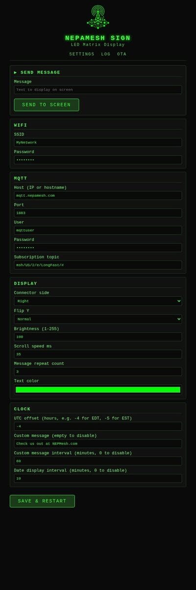
Fields worth calling out:
| Section | What's in there |
|---|---|
| WiFi | SSID, password — change networks without reflashing |
| MQTT | Host (accepts hostname or IP — firmware does its own DNS), port, user, password, subscription topic |
| Display | Connector side, Flip Y, brightness (1–255), scroll speed (ms/pixel), repeat count, text color (color picker) |
| Clock | UTC offset (e.g. -4 for EDT, -5 for EST), custom message + interval in minutes (0 = off), date display interval in minutes (0 = off) |
All settings write to NVS flash on Save & Restart. They survive power cycles and firmware updates.
Log
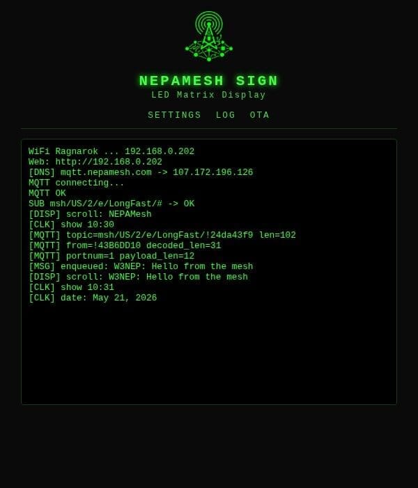
Same output as serial at 115200 baud, polling every second. This is where you go when something seems wrong. The device also broadcasts the same stream as UDP on port 4210:
nc -u -l 4210OTA
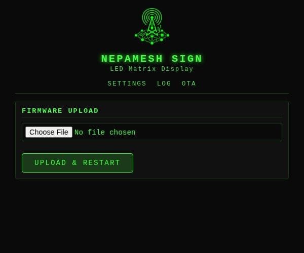
Build in PlatformIO, grab .pio/build/esp32c6/firmware.bin, upload it here. Device reboots into the new firmware. ArduinoOTA (port 3232, password-protected) is also active for direct PlatformIO OTA uploads — the esp32c6 target in platformio.ini already has the OTA upload port configured.
When Things Don't Work
Display blank after boot test
- Common ground between ESP32 and supply — this is the cause most of the time.
- Panel 5V from external supply, not the ESP32's 5V pin.
- GPIO 5 → resistor → panel DIN. Verify
LED_PIN 5in config.h matches your wiring.
Garbage pixels or wrong colors
- WS2812B is GRB byte order. FastLED handles this — don't change the
GRBtemplate argument. - Resistor on DIN. Without it, ringing on the 800 kHz signal causes bit errors.
- Cap across panel power pads. Without it, current spikes cause flicker under load.
Text mirrored or upside-down
Web UI → Settings → Display → toggle Connector Side and/or Flip Y. No recompile.
| Symptom | Fix |
|---|---|
| Text scrolls backwards | Change Connector Side |
| Text is upside-down | Enable Flip Y |
| Both | Change both |
Messages show as ?????
Non-default channel PSK. Replace the 16 bytes in MESH_KEY[] at the top of main.cpp with your channel's AES key and reflash.
Only seeing !XXXX, no callsigns
NodeInfo packets populate the cache. Trigger one manually from the Meshtastic app (Admin → Send NodeInfo) or wait — most nodes broadcast every 15–60 minutes. Cache is RAM only, doesn't persist across reboots, repopulates within an hour of traffic.
Clock not showing
Check the log for [CLK] NTP synced. If NTP hasn't synced, the clock is suppressed intentionally — a wrong time is worse than no time. NTP requires internet access, so confirm the device has a working WiFi connection first. Also verify the UTC offset in Settings → Clock is set correctly for your timezone.
MQTT not connecting
- Broker address in Settings → MQTT:
mqtt.nepamesh.com— no https://, no port in hostname. - Credentials: see the NEPAMesh MQTT setup guide.
- Unique client ID generated from chip MAC — not a collision issue.
- Weak WiFi signal is the most common cause of repeated disconnects.
Panel flickers under load
- Common ground between ESP32 and supply.
- Cap across panel power pads.
- Supply rating. At brightness 255 full white: ~3A. Default brightness 40 is intentionally conservative. Check Settings → Display → Brightness if you've cranked it.
Linux: permission denied on flash
Either usermod wasn't run, you didn't log out and back in, or the udev rules didn't apply. Go through the Linux setup steps again. Closing a terminal tab is not a logout.
Project Structure
led-mqtt-meshtastic-8x32/
├── platformio.ini     Board targets, lib_deps (FastLED, PubSubClient), OTA config
└── src/
    ├── config.h       Compile-time defaults  ← only file you need to edit
    ├── font5x7.h      5×7 pixel font, ASCII 32–126, column-major byte order
    └── main.cpp
         ├── UDP log ring buffer + broadcast
         ├── NVS settings load/save
         ├── FastLED matrix + XY() serpentine mapping
         ├── Scroll buffer and render loop
         ├── NTP clock + scheduled message timers
         ├── Node name cache (32 entries, RAM only)
         ├── Message queue (4 slots, ring buffer)
         ├── Minimal protobuf parser (no library)
         ├── AES-128-CTR decrypt (mbedTLS)
         ├── MQTT callback + port dispatch
         ├── WiFi connect + captive portal AP fallback
         ├── Web server: settings, log, OTA (/)
         ├── ArduinoOTA (port 3232)
         └── Boot LED test animation
Full source: github.com/nepamesh/led-mqtt-meshtastic-8x32
Part of the NEPAMesh project. Meshtastic is a registered trademark of Meshtastic LLC. No affiliation. No warranty. Build stuff.